|
|
API 16.919 PT serial cables |

PT offers a range of serial cables to easily connect PT instruments with RS232 to your computer.
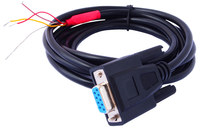
RS-232C cable DB9-tails.
Part A-CAB-232-DB9
This cable has a female DB9 connector at one end to connect to your PC or laptop and individual wire tails at the other end to connect to the RS-232C port of an indicator or transmitter. A USB adapter is available as an optional purchase if your computer does not have an RS-232C port.
To simplify the 3 wire connection required by PT instruments the cable
is configured as a null modem cable per the above illustration. The cable
has 3 wire tails with the following colour code.
BROWN: Pin 2 of
the connector, data to be received by the PC from the instrument.
RED: Pin 3 of the connector, data transmitted by the PC to the instrument.
YELLOW: Pin 5 of the connector. Signal ground.
SILVER: This
is a screen wire to protect the cable from interference. Connect to frame
ground in an electrically noisy environment.
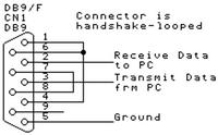
When connecting to an instrument, take note of the connection diagrams
in the instrument manual. Generally PC receive data will connect to instrument
transmit data, PC transmit data will connect to instrument receive data
and the signal ground (YELLOW) will connect to the instrument RS-232C
ground.
RS-485 cable USB-tails.
Part A-CAB-485-USB
This cable interfaces the USB port of a PC to the RS-485 port of PT instruments. The cable has a USB plug at one end and individual wire tails at the other. Installation of an FTDI driver may be required, but PT have verified that on Windows 7 (connected to the internet), OSX and Linux the driver has been automatically installed. A driver is provided with PT instruments with RS-485 connectivity in the event that Windows fails to automatically install the driver or the computer does not have internet connection
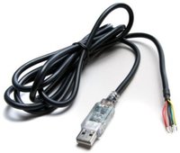
Cable connections are;
RED: 5V positive power source from the
USB interface. (Insulate if unused.)
BLACK: Signal and 5V ground.
YELLOW: Data - (B)
BROWN: Termination
resistor (120 Ω) connection 1
ORANGE: Data + (A)
GREEN: Termination
resistor (120 Ω) connection 2
If termination resistors are not provided elsewhere, connect GREEN
together with ORANGE and BROWN together with YELLOW.
Connect the
cable to the PT instruments as shown in the relevant manuals.
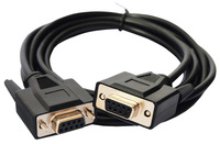
RS-232C cable DB9F/F-Null Modem.
Part A-CAB-232-DB9S
This cable has a female DB9 connector at each end and has cross over wiring to provide a null modem cable with full hand shaking. The cable will connect a computer with an RS-232C port or USB port (additionally requiring the RS-232C Adapter USB-DB9 cable part A-CAB-232-USB) to the PT252. Note: This cable is not handshake looped and for a 3-wire serial connection (like the PT252) it may be necessary to disable handshaking in your software.
RS-232C to USB adapter.
Part A-CAB-232-USB
Modern computers, desktops, laptops and tablets often do not have an RS-232C port but are equipped with a USB port. The A-CAB-232-USB adapts the USB port to an industry standard RS-232C port. Cables that would normally connect to a PC RS-232C port will connect to our adapter. The A-CAB-232-USB is recognised by Windows 7 (connected to the internet), OSX and Linux and the driver is automatically installed. A driver is provided with the cable for connectivity in the event that Windows fails to automatically install the driver or the computer does not have internet connection.
